Can a Multimeter Test VFD Performance?
With the continuous advancement of industrial automation, Variable Frequency Drives (VFDs) have become indispensable equipment across various industries and operating conditions. While VFDs incorporate multiple protection functions (overcurrent, overvoltage, overload protection, etc.), how can end-users verify their performance without specialized equipment?
Oulu Electric's technical team provides a practical guide for basic VFD assessment using just a multimeter:
Safety Notice & Step-by-Step VFD Testing Guide
⚠ Critical Safety Precautions:
Power OFF the equipment completely
Disconnect ALL input cables (R/S/T) and output cables (U/V/W)
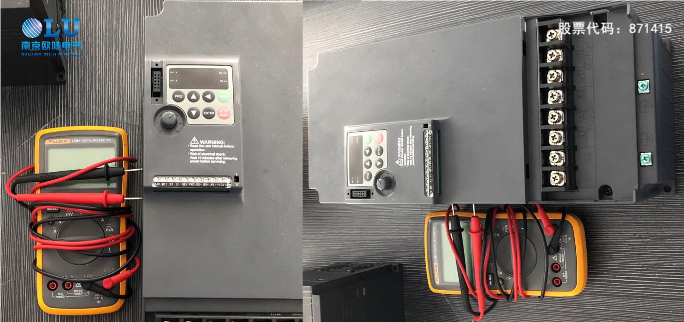
Verify capacitor discharge (measure DC bus voltage <10V before proceeding)
Testing Procedure Using Diode Mode:
1. Rectifier & Pre-charge Circuit Check
Set multimeter to diode test mode
Test 1:
Black probe to P(+), red probe to R/S/T sequentially
Record all three values
Test 2:
Red probe to N(-), black probe to R/S/T sequentially
Record all three values
Interpretation:
Normal: 6 readings show similar values (0.3-0.7V)
Fault: Significant variation indicates damaged diodes/pre-charge resistors
Symptom: No power display if faulty
2. IGBT Module Verification
Test 1:
Red probe to P(+), black probe to U/V/W sequentially
Record values
Test 2:
Black probe to N(-), red probe to U/V/W sequentially
Record values
Interpretation:
Normal: 6 balanced readings
Fault: Abnormal values indicate IGBT damage
Symptom: No output or fault alarms
3. Dynamic Performance Test
Connect matched induction motor (no load)
Gradually reduce frequency from 50Hz to minimum
Monitor current with clamp meter:
Good VFD: Current remains stable during frequency change
Faulty VFD: Current fluctuates abnormally
Limitations & Recommendations:
This method only checks power stage components
For comprehensive evaluation:
Use oscilloscope for PWM waveform analysis
Perform insulation resistance tests
Check control board signals
Always consult manufacturer for:
Detailed test procedures
Firmware diagnostics
Load testing protocols
Oulu Electric Technical Tip:
For EV510/EV510H series VFDs, additional self-test functions can be accessed by:
Press [MENU] + [ENTER] for 5 seconds
Navigate to "Diagnostic Mode"
Select "Auto-test" routine
Remember: These tests should be performed by qualified personnel only. When in doubt, contact our technical support with your VFD model and test readings.