Two Common Methods for Motor Control Using Nanjing Euroverter Frequency Converters:
Variable Frequency Drive (VFD) speed control technology represents a crucial advancement direction in modern electric drive systems. As the core component of VFD systems, the performance of the frequency converter itself has become an increasingly decisive factor in determining speed regulation quality.
Beyond the inherent manufacturing quality of the VFD, the control strategy employed is equally critical. Today, we introduce two commonly used motor control methods implemented in Nanjing Euroverter frequency converters for your reference:
After connecting the main power supply to the VFD, motor control requires wiring external control circuits to the appropriate terminals and setting the VFD’s start mode parameter to external operation.
Two common methods for controlling motor operation are:
Switch Control
Relay Control
1. Switch Control (Forward Rotation Circuit)
This method uses a manual switch connected to terminal S1 (S1-COM closure) to control motor rotation.
Working Principle:
Power-On Preparation
Auxiliary contact latches KM (self-holding).
Main contact supplies power to the VFD.
Press the start button → Contactor KM coil energizes.
KM main and auxiliary contacts close:
Forward Rotation Control
Press S1 (connected to S1-COM) → VFD receives a forward run signal.
U/V/W terminals output power → Motor runs forward.
Adjust potentiometer R to change frequency (motor speed).
Fault Protection
If the VFD faults, its internal S1-COM contact opens → KM de-energizes → Cuts VFD power.
Stop Control
Open S1 → VFD stops output → Motor halts.
Press STOP → KM de-energizes → Disconnects VFD input power.
2. Relay Control (Forward Rotation Circuit)
This method uses a relay (KA) for automated control.
Working Principle:
Power-On Preparation
Supplies VFD power.
One auxiliary contact latches KM.
Another prepares relay KA for operation.
Press S1 → KM energizes.
KM main & auxiliary contacts close:
Forward Rotation Control
Latch KA (self-holding).
Bypass S1 (prevents accidental shutdown).
Close S1-COM → VFD runs forward.
Press S2 → KA energizes.
KA contacts:
Adjust R to change motor speed.
Fault Protection
VFD fault → Internal B-C contact opens → KM & KA de-energize → Cuts VFD power.
Stop Control
Must stop VFD before cutting power via S1 (relay KA bypasses S1 during operation).
Press S3 → KA de-energizes → VFD stops.
Safety Feature:
Nanjing Euroverter Terminal Parameter Settings
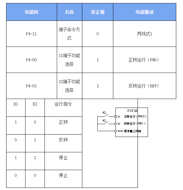
Mode 0: Two-wire control (basic start/stop).
Mode 1 (Commonly Used):
S1 = Forward
S2 = Reverse
Allows direct motor control via terminals.
Key Advantages
✔ Switch Control: Simple, manual operation.
✔ Relay Control: Safer, prevents accidental power cuts.
✔ Energy & Protection: Fault detection + smooth start/stop.
For optimal performance, ensure correct wiring and parameter settings. Nanjing Euroverter VFDs provide reliable, efficient motor control for industrial applications.
Motor Control Modes in Nanjing Euroverter VFDs
1. Two-Wire Control Mode (Standard Forward/Reverse)
Operation Logic:
2. Two-Wire Mode with Direction Control (Alternative Configuration)
Terminal Functions:
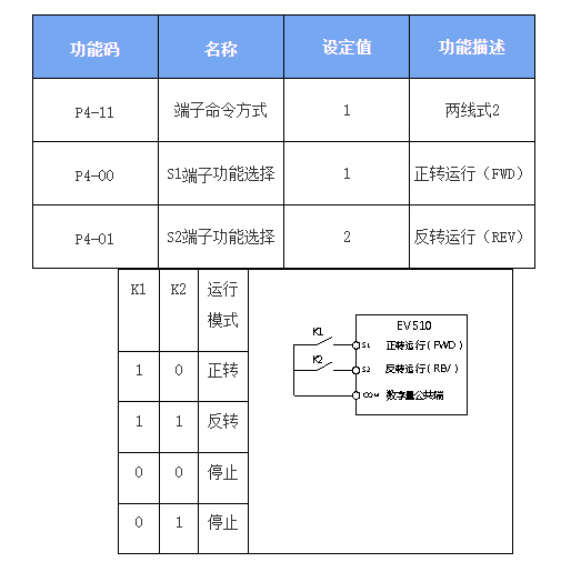
Figure 6-9: Two-Wire Control Mode 2
As shown in the diagram, this control mode operates as follows:
With K1 closed:
K2 open → Inverter runs forward
K2 closed → Inverter reverses
K1 open → Inverter stops immediately
2: Three-Wire Control Mode
1: Terminal Functions for This Mode:
S3: Enable terminal
S1 & S2: Direction control (forward/reverse)
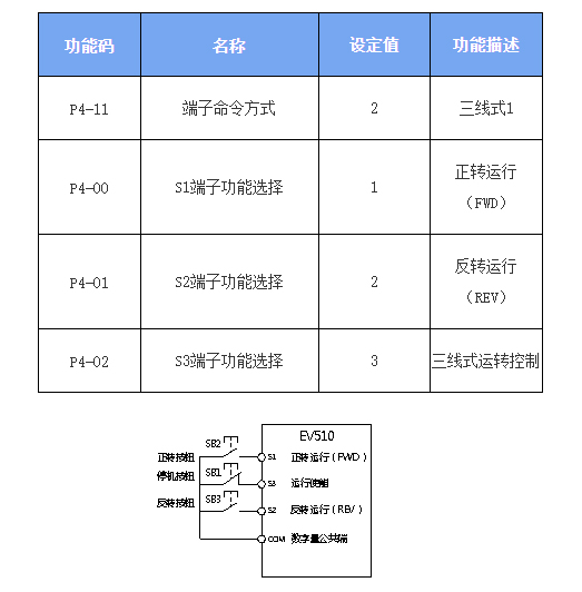
As shown in the figure above, in this control mode:
Basic operation:
Pressing the SB2 button → Inverter operates in forward rotation
Pressing the SB3 button → Inverter operates in reverse rotation
With the SB1 button held closed:
When the SB1 button is released → Inverter stops immediately
Control characteristics:
SB1 must remain continuously closed during normal startup and operation
SB2/SB3 buttons use rising edge triggering and take effect immediately upon pressing
The inverter's operating state is determined by the last valid operation of these three buttons
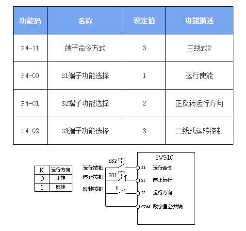
As illustrated in the diagram, this control mode operates as follows:
With SB1 button engaged (closed state):
Pressing SB2 activates operation
K open → Forward rotation
K closed → Reverse rotation
Immediate release (opening) of SB1 triggers instant inverter shutdown
Operational requirements:
SB1 must remain continuously closed during normal startup and operation
SB2 commands take immediate effect upon button press (rising edge trigger)
The above describes two common motor control methods using Nanjing Euroverter frequency converters. We welcome valuable feedback.
Note: The control method selection is a critical research topic as:
Different operation modes require distinct capacity calculation approaches
Selection criteria vary accordingly
Specific conditions must be satisfied
During application, users should configure detailed parameters based on actual product specifications to ensure optimal performance.