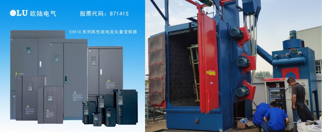
Nanjing Oulu Frequency Converter Interference Solutions

Solutions for Frequency Converter Interference Issues
1. Software-Based Anti-Interference Measures
Adjust Carrier Frequency:
Reduce the carrier frequency via the converter's HMI to an appropriate range.
If ineffective, proceed with hardware solutions.
2. Proper Grounding
Effective grounding suppresses external interference and minimizes device emissions.
Implementation:
(a) Converter Grounding:
Connect the main circuit terminal PE (E/G) to a dedicated ground rod (not shared with other equipment).
Ground wire: ≥4mm² cross-section, ≤20m length.
Keep away from low-voltage device grounding points.
(b) Other Equipment Grounding:
Separate protective ground and working ground with independent ground rods.
Route shielded control and power cables to separate ground points before connecting to the main electrical ground.
3. Shielding the Interference Source
Converter Housing: Use an iron enclosure to contain EMI.
Output Cables: Shield with steel conduits.
Signal Cables:
Use shielded twisted pairs (STP) for control signals (e.g., 4–20mA).
Keep signal lines short (≤20m) and physically separate from power lines (AC380V/AC220V).
Never run signal and power lines in the same conduit or duct.
4. Optimized Cable Routing
Keep power/signal lines far from converter I/O cables.
Avoid parallel routing of other equipment cables with converter lines.
If Interference Persists, Apply These Additional Measures:
5. Interference Isolation
Use isolation transformers between power supplies and sensitive devices (controllers, transmitters).
Noise isolation transformers block conducted interference.
6. Installing Filters
Filters suppress interference propagation via power lines.
Types of Filters:
(1) Input Filters
Line Filter (Inductive): Blocks high-frequency harmonics.
Radiated Filter (Capacitive): Absorbs high-frequency noise.
(2) Output Filters (Inductive)
Never connect capacitors directly to the inverter output (risk of damaging IGBTs).
In LC filters, connect the capacitor side to the motor.
Reduces motor harmonic currents and torque ripple.
Critical Notes:
7. Installing Reactors
Suppresses low-frequency harmonics (5th, 7th, 11th, 13th) that degrade power factor.
Types of Reactors:
(1) AC Reactor (Input Side)
Improves power factor (0.75–0.85).
Protects against inrush current and voltage imbalance.
(2) DC Reactor (DC Link)
More effective for power factor correction (up to 0.95).
Compact and lightweight.
Interference Case Studies
1. External Device Interference
Symptom: Motor occasionally fails to stop despite proper shielding and filter use.
Root Cause: Strong magnetic fields from nearby high-current power distribution cabinets.
Solution: Relocate the converter cabinet away from the power room.
2. Converter-Induced Interference
Symptom: Motor does not start; 4–20mA signal shows 0Hz.
Root Cause: Signal interference from the converter.
Solution: Add a 102 capacitor at the transmitter output to filter noise.
Summary of Best Practices
✔ Input/Output Filters & Reactors
✔ Proper Shielding & Grounding
✔ Isolation & Cable Separation
✔ Carrier Frequency Optimization
For persistent issues, consult Nanjing Oulu’s 24/7 Technical Support: +86 159-5163-6558.